Get in Touch with Masstech

Updated: September 2026 · Author: Cherry · Reviewed against current public safety, controls, and packaging-industry sources
A bottle packaging machine is equipment within a connected production system that receives bottles in a defined condition and releases grouped, wrapped, or cased packs. The specification should therefore begin at the infeed handover and end at the discharge handover. The work between those points needs a rate basis, interface rules, changeover evidence, and acceptance criteria.
Quick answer
Before requesting equipment, define the line boundary, bottle and pack range, sustained good-pack rate, upstream/downstream signals, accumulation behavior, safe-intervention tasks, utilities and FAT/SAT evidence. Catalog speed becomes useful only after those conditions are attached to it.
This guide is for engineering, operations, and procurement teams preparing a line specification or acceptance plan. It does not compare models, publish prices, or replace a site risk assessment. If your scope is already defined and you want to review equipment options, use the bottle packaging machine configurations page. The sections below stay on the informational side of that boundary.
Define the Packaging Boundary Before You Specify Equipment
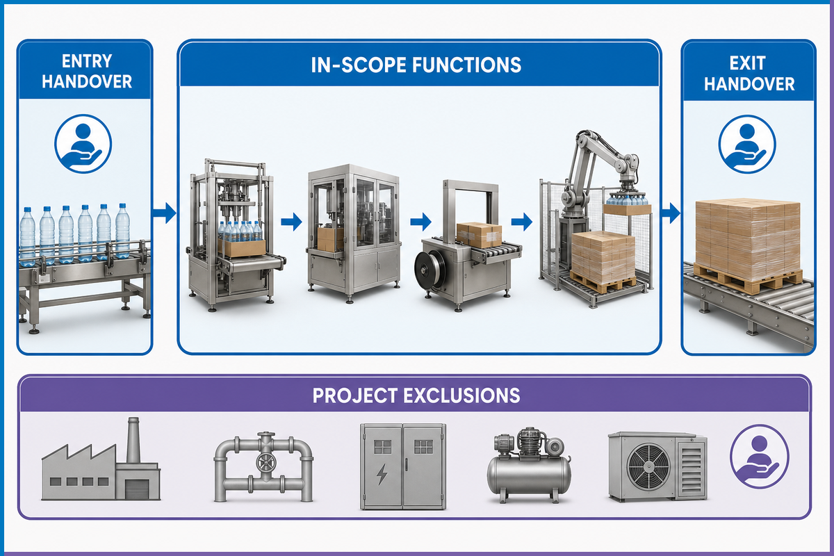
“Bottle packaging” can refer to primary packaging, secondary packaging, or an end-of-line system. Filling equipment puts product into the bottle. Capping equipment closes it. Labeling equipment applies or verifies product identification. Shrink wrappers, tray packers, and case packers group finished bottles for handling and distribution. Some projects may include several of these functions, but the category name does not prove which ones are inside the quote. For a separate operation that manufactures the empty folding cartons, consider folder gluer equipment from Cenwan; carton production is a different equipment scope from loading bottles into finished cartons.
The current ANSI catalog description for ANSI/PMMI B155.1-2023 covers primary, secondary, and tertiary packaging and the coordination of packaging and processing functions on a production line. That line-level scope is a useful reminder: the interfaces are part of the system definition, even when different suppliers own the machines.
Search results often mix this scope with upstream equipment. An automatic liquid filling machine, bottle filling system, or other liquid filling equipment meters product into containers; it can affect line efficiency but is not automatically the secondary packer discussed here. Keep that bottle filling boundary explicit, so filler accuracy and product-contact questions stay with the correct machine and owner.
Search labels such as water bottle packaging machine, commercial bottle packaging machine, and small bottle packaging machine describe a market, audience, or scale; they still do not define the functional boundary. Use the same entry-and-exit test for each label.
What is a packaging machine called?
The name depends on the function. Equipment that fills and closes the immediate container is normally primary-packaging equipment. Machines that group bottles in film, trays, cartons, or cases are secondary-packaging equipment. Palletizing and transport-unit preparation are often called tertiary or end-of-line packaging. Use the functional name in the specification, then write the exact entry and exit conditions. “Filled, capped, and label-verified bottles in; twelve-bottle shrink bundles out” is far less ambiguous than “complete bottle packaging line.” When specifying that transport unit, review pallet strapping and stretch film from UD Packaging separately from the equipment that fills and closes individual bottles.
Draw a one-page boundary diagram before discussing machine size. Mark the last upstream condition that the project accepts, the first downstream condition it guarantees, and every dependency that remains outside the purchased scope. This short exercise exposes missing conveyors, coding, inspection, reject handling, case supply, and pallet-flow responsibilities early.
Write exclusions beside the diagram, not in a later email. For example: product-filled bottles are supplied by others; cap and label quality remain upstream responsibilities; empty cases arrive at a stated orientation; finished cases leave at a stated height; palletizing is outside scope. Then name who supplies each connecting conveyor, guard extension, control cable, and line-level stop function. The boundary is ready only when a third person can read it and identify both sides of every handover.
Build an Interface Control Document for Every Machine Handover
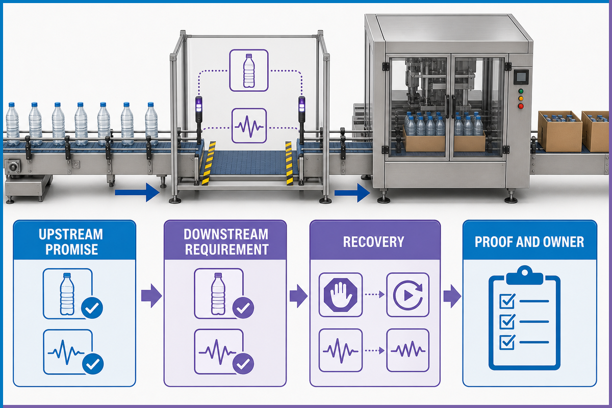
A machine can pass an isolated shop test and still fail in the assembled line. Bottles may arrive with the wrong pitch, a downstream stop may not propagate upstream, a reject may have no confirmed destination, or both machines may wait because each expects the other to restart first. The cure begins with an interface document written per physical handover.
OMAC’s HMI and stack-light guidance maps PackML states to consistent displays and controls. Packaging World’s PackML coverage also explains how a common state model and consistent tags help multi-vendor equipment communicate. That vocabulary is valuable, but a familiar state name is not proof that the bottles, signals, and recovery sequence work. The project still needs a testable record, consistent with the coordinated-line scope in ANSI/PMMI B155.1-2023.
The Interface Handshake Record takes the condition promised by the upstream machine, compares it with the downstream requirement, and assigns a verification method. Its output is a decision: the boundary is ready for design freeze, or a named mismatch remains open.
| Interface field | Upstream promise | Downstream requirement | Proof and owner |
|---|---|---|---|
| Bottle condition | Filled, capped, dry, label verified | Stable base; no loose cap or wet surface | Approved samples and inspection record |
| Flow | Rate window and discharge pitch | Accepted pitch, surge and orientation | Measured run at the handover |
| States and signals | Ready, running, held, starved or blocked | Matching meaning, timing and fail state | I/O test and event trace |
| Reject ownership | Reject identity and tracking status | Confirmed removal or controlled stop | Challenge samples and count reconciliation |
| Recovery | Restart permissive and retained product state | Known sequence without collision or orphan product | Scripted stop/restart test |
Repeat the record at every boundary: unscrambler to filler, filler to capper, capper to bottle labeling machine, labeler to packer, and packer to case or pallet handling where those functions are in scope. One global controls note cannot describe all of these handovers.
Convert Nameplate Speed into a Sustainable Pack-Rate Requirement
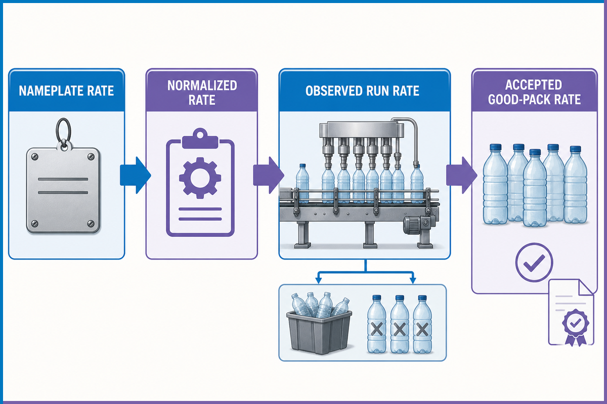
Nameplate speed is normally stated for one machine, one unit, and a defined operating condition. Fillers may be described in bottles per hour, while case packers are measured in cases per minute. Comparing those numbers directly creates false headroom.
Start with deterministic conversion. If the incoming flow is 12,000 bottles per hour, divide by 60 to obtain 200 bottles per minute. At that same bottle flow, the theoretical packaging rates are:
- 6 bottles per pack: 200 ÷ 6 = 33.33 packs per minute.
- 12 bottles per pack: 200 ÷ 12 = 16.67 packs per minute.
- 24 bottles per pack: 200 ÷ 24 = 8.33 packs per minute.
Those are unit conversions, not accepted output. Availability losses, small stops, speed loss, rejects, and startup waste still sit between theoretical flow and good packs. OEE separates availability, performance, and quality for this reason, but this guide does not impose a universal OEE target. The contract should name what counts as scheduled time, an allowed exclusion, a stop, and a good pack.
The Rate-Promise Ledger keeps four quantities separate: quoted nameplate rate, normalized theoretical pack rate, observed gross run rate, and accepted good-pack rate. Its output is a rate decision tied to one SKU and one test window.
| Ledger field | Value to record | Why it changes the decision |
|---|---|---|
| Unit basis | Bottles/min and packs/min, with bottles/pack | Prevents unlike-rate comparison |
| Material/SKU | Bottle, closure, label, film/carton and pattern | Binds performance to the tested condition |
| Observation window | Start/end, planned pauses and exclusion rules | Stops a short burst from becoming the reported rate |
| Good output | Accepted packs, rejects and rework | Separates motion from saleable output |
| State loss | Held, starved, blocked and fault duration | Shows where the active constraint moved |
Use brochure or data-sheet fields as question inputs, not as acceptance results. The commercial Bottle Packaging Machine page owns model, package-envelope, utility and operating-range details. This guide keeps a different job: turn each offered field into a witnessed test question. Which SKU and pack pattern support the stated rate? Where are utility measurements taken? Which approved material, observation window and good-pack rule will prove the result? That preserves the distinction between researching an acceptance method and comparing a commercial configuration.
The Krones FAT test guideline also warns that a test setup can operate below rated speed when recirculation is not available. Record such a limitation before the test. For asynchronous lines, a NIST finite-buffer simulation resource illustrates why one machine’s rate cannot describe every system interaction. Neither side should silently convert a constrained setup into a machine failure or waive the contractual rate without an agreed disposition.
Size Accumulation Around Stop Patterns and Fault Recovery
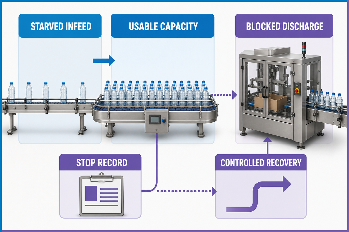
After translating the required pack rate, size accumulation around the stop pattern that threatens it. Accumulation buys time between machines. It does not repair a recurring jam, fix an unstable bottle, or decide which machine restarts first. A buffer can even hide the event that needs attention until the line becomes harder to empty and recover.
A simple timing estimate is still useful. If a conveyor holds 240 usable bottles and the upstream rate is 200 bottles per minute while the downstream machine is stopped, the gross coverage is 240 ÷ 200 × 60 = 72 seconds. “Usable” matters: physical capacity near a transfer, curve, or sensor may not be controllable capacity. If both machines continue at different rates, size against the net rate difference instead of total upstream flow.
Then compare that estimate with the stop record. Ask how often the downstream event occurs, its median and upper-range duration, whether the upstream machine can stop safely, how long the downstream machine takes to recover, and whether the buffer can discharge without creating a new surge. A NIST manufacturing-simulation resource models finite buffers, asynchronous behavior, degradation, and maintenance. That is a useful boundary on the arithmetic: one average stop is not enough to certify a highly variable or tightly coupled line. Use trials or an appropriate line model when variability matters.
What are the common problems with packing machines?
Watch for starved infeed, blocked discharge, unstable bottle spacing, material-feed faults, reject-count mismatch, repeated short stops, and restart jams. Record the neighboring machine state before assigning ownership. Use the record to distinguish a local machine problem from a line-level condition.
Field note: A buffer that empties only under ideal bottle spacing is not fully usable capacity. Record the controllable count at each transfer, then test how the line stops and recovers.
Buffer evidence to keep
- Timestamped starved and blocked states
- Usable bottle capacity by SKU
- Stop duration and recurrence
- Upstream stop response
- Downstream recovery and discharge time
What it cannot prove alone
- That the recurring fault is acceptable
- That every bottle remains stable
- That rejects retain identity
- That the restart sequence is safe
- That more conveyor raises good-pack output
Map the SKU Operating Envelope Before Changeover Proof
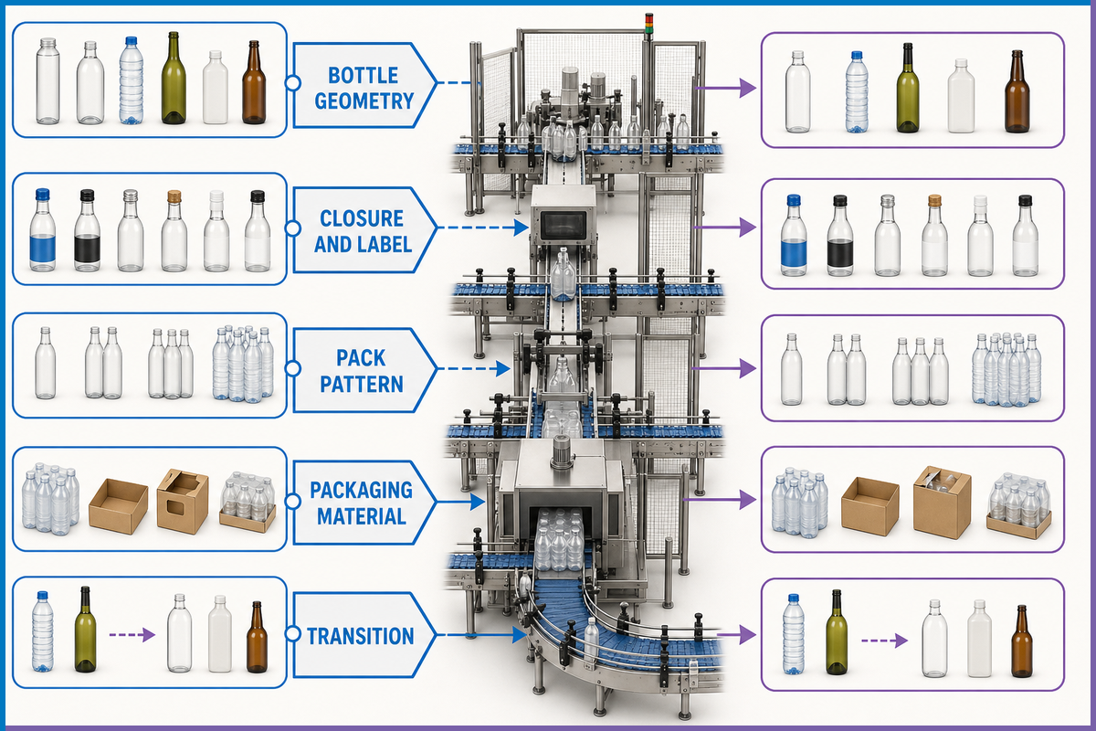
Accumulation only helps if each SKU remains controllable at the handover. A saved recipe proves that a set of digital values exists. It does not prove that guides, lanes, grippers, film, cartons, inspection settings, and product tracking have moved to the correct condition. Nor is one “worst SKU” always worst for the whole line. A tall narrow bottle may challenge stability; a short bottle may challenge sensing; one closure may change cap height; one pack pattern may load the wrapper or case packer hardest.
Build a SKU operating-envelope table before choosing test samples. Each row names the bottle and pack, while each column exposes a station-specific edge condition. That lifecycle evidence supports the line-level machinery scope described by ANSI/PMMI B155.1-2023.
| Dimension | Boundary question | Evidence |
|---|---|---|
| Bottle geometry | Which SKU has the smallest base, highest center of mass or widest tolerance? | Approved drawing, samples and observed handling |
| Closure and label | Do cap height, tamper band or label edge change detection and guides? | Setup reference and inspection challenge |
| Pack pattern | Which count and lane arrangement changes grouping logic most? | Pattern recipe, change parts and verified bundle/case |
| Packaging material | Which film, tray or carton has the narrowest acceptable process window? | Material specification and tested lot |
| Transition | Which from/to pair changes the most independent settings? | Timed change, verification steps and first-good-pack record |
Can filling equipment handle multiple container sizes?
Often yes, but the answer belongs to the connected line, not the filler alone. Confirm container dimensions, stability, neck and closure, label condition, conveyor guides, sensing, pack pattern, change parts, setup references, and inspection settings. Choose station-specific edge cases and high-change transitions for FAT, then repeat the site-dependent conditions during SAT. A stored recipe name is one input to that proof, not the proof itself. Confirm each setting during a documented changeover for the selected SKU before accepting the result.
Lock Utilities, Controls and Safe-Intervention Boundaries
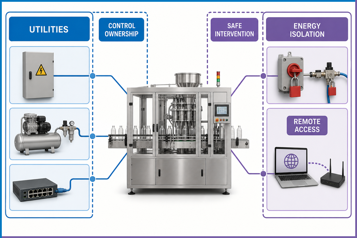
Utility and controls questions are cheap on a drawing and expensive after installation. Freeze the voltage and frequency, available current, protective arrangement, compressed-air pressure and quality, heat rejection or exhaust, floor loads, drains where applicable, ambient limits, network boundary, cable routes, and measured conditions for SAT. Record both the required range and the party responsible for delivering it.
Safety scope also crosses supplier boundaries. ANSI/PMMI B155.1-2023 addresses machinery and coordinated production-line functions across relevant lifecycle phases. For U.S. work within its scope, OSHA 29 CFR 1910.147 covers servicing and maintenance where unexpected energization, startup, or stored-energy release can injure an employee. Normal production is not covered without distinction; the rule describes conditions that bring production-time servicing into scope and a narrow exception for routine, repetitive, and integral minor servicing performed with effective alternative protection.
That means the specification should list tasks, not make one vague statement about lockout. For each jam clear, clean, adjustment, setup, tool change, and inspection, the employer and qualified project parties determine the hazards, safe state, energy isolation, alternative protection where permitted, access, and training. Push buttons and selector switches are not energy-isolating devices under the OSHA definition.
Connected controls add another boundary. Name the owner of remote vendor access, authorized accounts, approval window, logging, network segmentation, approved software and firmware baseline, backups, restore test, and configuration-change record. These fields do not turn the article into a cybersecurity standard. They prevent “remote support included” from becoming an unmanaged permanent path into the line.
Write a FAT Protocol Around the SKU Operating Envelope
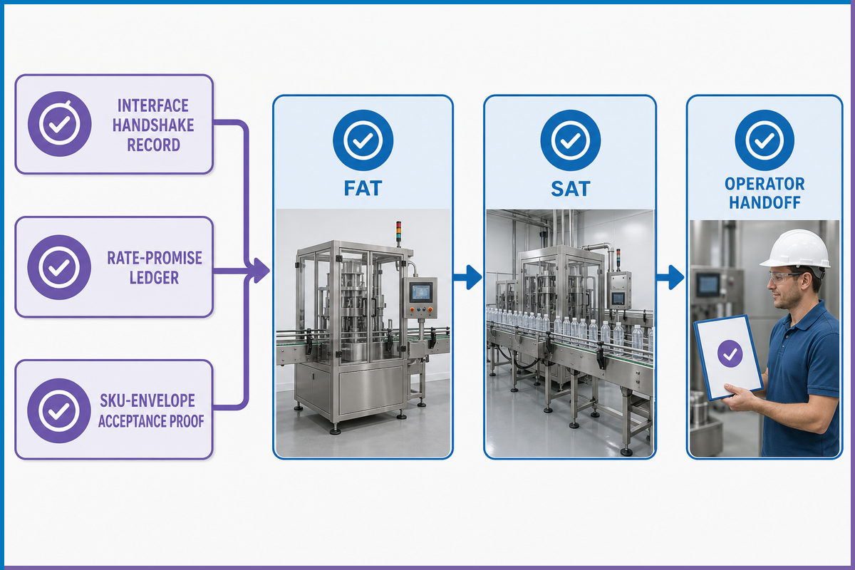
A factory acceptance test should answer contract questions before shipment. A demonstration answers only “did it run now?” The protocol should identify the requirement, approved material, setup condition, observation method, pass criterion, evidence file, and disposition route before the witness arrives. In regulated operations, the FDA qualification and process-validation boundary remains separate from this supplier test.
The SKU-Envelope Acceptance Proof is the traceability layer. Its input is the requirements list plus the station-specific edge conditions from the SKU matrix. Its output is a covered/not-covered decision for each requirement, with an owner and due date for every deviation. That is different from the Interface Handshake Record, which decides boundary readiness, and the Rate-Promise Ledger, which decides rate acceptance.
| FAT block | State before the test | Evidence to retain |
|---|---|---|
| Material identity | Bottle, closure, label, film/carton lot and approved substitutions | Sample register and photos |
| Sustained run | Unit basis, window, exclusions, good-pack definition | Counts, state durations, rejects and event log |
| Interface behavior | Signal list, simulated neighbors and limitations | I/O trace and witnessed stop/restart |
| Changeover | From/to pair, start/end definitions and personnel | Setup verification, time and first-good-pack result |
| Fault and recovery | Approved challenge, safe method and expected state | Alarm, product disposition and restart sequence |
| Deliverables | Drawing, manual, backup, spares and training list | Revision-controlled package and open-item log |
| Safety functions | Approved validation plan, devices, zones and reset behavior | Witnessed results and responsible-party signoff |
| Digital baseline | Approved software, firmware, accounts and remote-access condition | Version list, backup and restore evidence |
The Krones test guideline treats contract scope, test materials, connected interfaces, production runs, alarms, emergency-stop/restart, changeover, and deviations as explicit parts of a supplier-side test. Exact duration and sample quantity remain contract-specific. The protocol should also record if a full recirculation loop or actual neighboring machine is absent.
Mass Technology’s public solution page states recipe-based changeover, a pre-engineered conveyor handover, and FAT before shipment. Those are supplier statements, not independent test results. Convert them into questions: Which settings are in the recipe? Which mechanical checks remain? What exact handover range was engineered? Which FAT record will show that it passed? The Mass Technology engineering team can answer project-specific scope questions against the same written protocol.
Turn FAT Results into a Site Acceptance and Handoff Plan
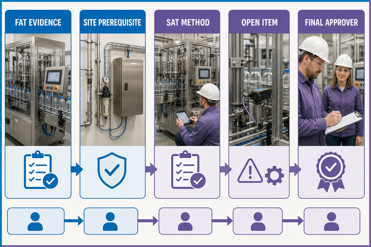
FAT happens in the supplier environment. SAT happens after installation, when actual utilities, operators, materials, networks, and adjacent machines exist. One does not repeat every other test, but every requirement needs a disposition: proved at FAT and accepted, held for site conditions, re-tested at site, or open with an owner.
Create the SAT register before shipment. Carry forward interface limitations, approved substitutions, software versions, unresolved deviations, utility prerequisites, guarding work, network tasks and training needs. A practical row is the FAT evidence ID, shipment hold point, site prerequisite, SAT method, witness, result, open item and final approver.
- Measure the installed electrical and compressed-air conditions under load.
- Retest real upstream/downstream signals, accumulation and stop propagation.
- Run production materials through the reject path and reconcile counts.
- Observe a controlled recovery with site roles, not only supplier technicians.
- Confirm backups, spare/change parts, drawings, and revisions match the installed machine.
- Close or formally accept every deviation; do not let an email thread become the register.
Regulated plants may need more. FDA inspection guidance for regulated packaging contexts discusses installation qualification and process validation across established operating limits. FAT and SAT do not replace IQ, OQ, PQ, process validation or revalidation where the product, process and jurisdiction require them. This guide provides a machine-project handoff structure, not a regulated validation protocol.
Design for Training, Maintenance and Skill Retention
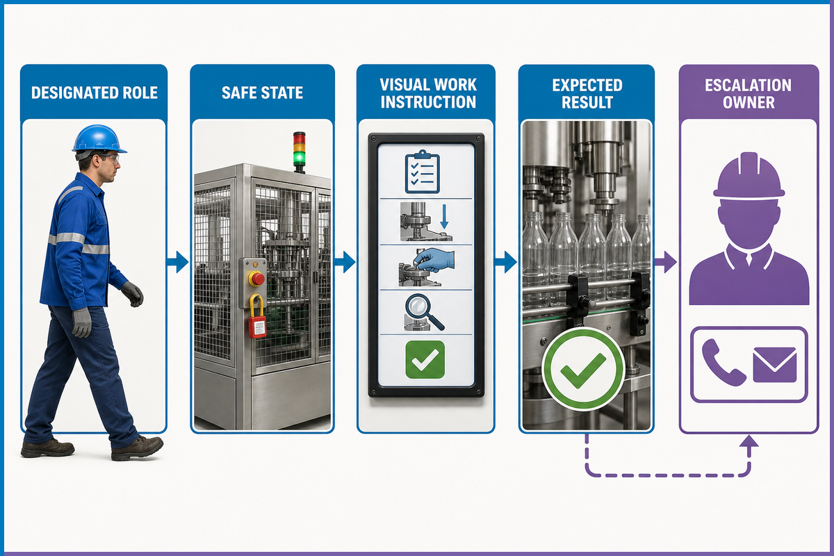
A line is not accepted merely because the commissioning engineer can run it. The handoff must show that designated site roles can start, stop, change, recover, inspect, and escalate within approved procedures.
PMMI’s 2025 workforce study used an online survey of 136 end-user and OEM respondents plus 14 qualitative interviews. It highlights interest in machine-embedded HMI guidance, predictive alerts, remote OEM support, short task videos, QR-linked documentation, and targeted changeover automation. The sample does not prove that one format fits every plant. It does show why a large manual alone is a weak handoff plan.
Build an intervention-to-instruction matrix. For each recurring task, name the role, prerequisite training, safe state, HMI path, visual work instruction, tools or change parts, expected result, alarm/escalation owner, and record retained. Test the material during FAT or SAT by having the intended role perform the task. If the only person who can recover a common stop is the visiting engineer, the handoff is incomplete across the machinery lifecycle scope identified by ANSI/PMMI B155.1-2023.
Acceptance question
Can a trained operator use the delivered instruction to complete the approved task, recognize the expected machine state and know when to stop and escalate—without relying on a private message or one person’s memory?
Frequently Asked Questions
What is a bottle packaging machine?
A bottle packaging machine is equipment, or a connected end-of-line system, that receives bottles in a defined condition and produces grouped, wrapped, trayed, cartoned, cased, or otherwise shipment-ready units. The project definition should name the exact handover states. Filling, capping, and labeling may be included dependencies, but the phrase alone does not put them inside the purchased scope.
How much does a bottle packaging machine cost?
Price depends on scope: one wrapper versus a connected line with conveyors, case handling, controls, guarding, installation, and commissioning. This informational guide does not publish price bands because configuration and quotation belong on the commercial solution page. Define the interfaces and acceptance document first, then request a quote against that same scope.
What are the common problems with packing machines?
Common line-level symptoms include starved infeed, blocked discharge, unstable bottle pitch, film or carton feed faults, sensor disagreements, lost reject identity, small repeated stops, and weak recovery sequences. Record what neighboring machines reported before the event. The component that stopped may not be the source of the condition. Any inspection or intervention must follow the plant’s approved guarding and hazardous-energy procedures.
Can one packaging line handle multiple bottle sizes?
Often, but prove compatibility across bottle dimensions, stability, closure and label condition, pack pattern, packaging material, change parts, setup references, and inspection settings. Test edge cases and high-change transitions, not only the smallest and largest bottle in the selected SKU range.
What is the difference between FAT and SAT for packaging equipment?
FAT is performed before shipment in the supplier environment against agreed samples, rates, interfaces, changeovers, faults, and deliverables. SAT tests the plant-dependent conditions after installation: actual utilities, materials, operators, networks, and neighboring machines. A FAT pass does not erase site prerequisites, while SAT should not become an unstructured renegotiation. The register shows what was proved, what must be re-proved, and who owns every deviation.
What documents should be delivered with a bottle packaging line?
Typical deliverables include approved drawings, interface and utility schedules, instructions, backups, spare- and change-part lists, FAT records, an open-deviation register, training records, and the SAT plan. The package should show revision status, acceptance evidence, and items still due after shipment.
Use the 3-Record Acceptance Chain
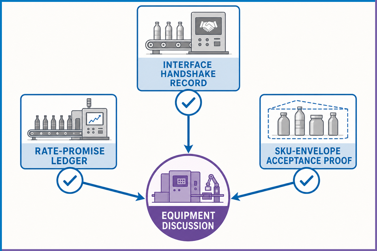
The three named records do different jobs within the coordinated production-line scope described by ANSI/PMMI B155.1-2023. The Interface Handshake Record decides whether adjacent machines can exchange product and state. The Rate-Promise Ledger decides whether observed good output meets the agreed rate basis. The SKU-Envelope Acceptance Proof decides whether the test set covers each station’s material and changeover edge cases and closes the resulting deviations.
Build them in that order. A rate run is hard to interpret when the interface is undefined, and a FAT result is incomplete when the tested SKU set ignores a station’s operating boundary. If you are ready to convert these requirements into an equipment discussion, review the available end-of-line configurations and send the same boundary, rate, and SKU records with the inquiry. The same bottle packaging machine scope can help frame the commercial discussion, but the written records remain the acceptance basis.
Have a defined bottle and pack range?
Bring the line boundary, target good-pack rate, SKU envelope, utility schedule and acceptance questions. That gives engineering and commercial teams one testable starting point.
References and Research Basis
References & Sources
Did this guide meet its evidence standard? The publication was reviewed against selected U.S. regulations, a current packaging-machinery safety-standard catalog, trade-group controls guidance, packaging-industry technical reporting, a workforce study, manufacturer-side test guidance, and a government manufacturing-simulation resource. Practitioner discussions were used only as background, not as proof.
- OSHA 29 CFR 1910.147, Control of hazardous energy
- ANSI/PMMI B155.1-2023, Public scope and edition record
- OMAC, PackML HMI and stack-light guidance
- Packaging World, PackML integration and common machine states
- Packaging World, OEE loss categories and rate basis
- Krones, Manufacturer-side FAT test guideline
- PMMI, 2025 Inside the Workforce Gap
- NIST, Finite-buffer manufacturing simulation resource
- FDA inspection guidance, Qualification and process-validation boundary